Saturday, July 30, 2016

Setting up development environment for STM32F030: Software

I have looked for different environments for STM32 development and finally settled up with combination of Cygwin, Eclipse, GCC ARM corss-compiler and OpenOCD.

I will not get into deep for setting up everything since I did that a couple of months ago and do not remember all the details. I will try to put things here as a basic guideline for myself, just in case I need to setup everything from scratch. Hope it will be useful for others as well.

All instructions below are from GNU ARM Eclipse pages and are covered in much more detail than here. You can just skip reading and go to the Install Page. Also, all below is for Windows. Installation for other OSes is also covered in the Install Page.
  1. Install the ST-Link V2 device driver.  After the installation you should see 'STLink dongle' entry in the Device Manager:
  2. Download and install GCC for ARM cross compiler. In fact you need no real installer. Just get zip file, extract to some known place (for me it is c:\gcc-arm-none-eabi). No need to adjust path variables, registry, etc. Eclipse will do it for you.
  3. Download and install OpenOCD. Again, I didn't use any installer package, just extracted archive.
  4. Download and install JRE. I have got JRE8u91 64-bit. To my surprise Oracle now supplies JRE packages for Windows that do not require install. This is amazing since I hate 'update me forever' puke that was installed by JRE and JDK in previous versions.
    Yet again, I have extracted the archive into c:\jre-8 without updating anything.
From now on I just followed the  "How to install the GNU ARM Eclipse plug-ins?" page with slight variations:
  1. I have Cygwin, so I don't need extra build tools for Windows. I just start Eclipse from Cygwin bash and have /cygdrive/c/jre-8/bin in my PATH.
  2. I didn't install QUEMU
  3. I have installed ARM plugins as described in the "The Eclipse update site way" section on that page.
  4. It is very important to follow instructions in "Download CMSIS Packs" section on that page. Otherwise you will not see your processor peripheral's registers while debugging.
  5. For Eclipse noobs like me it is highly recommended to set-up Workspace Preferences
  6. I have installed Eclipse EGit for version control and Github integration
  7. Sometimes Eclipse does not pass Pause and Stop commands to OpenOCD. I didn't figure yet whether it is a bug or just something wrong in my setup. When this is happen I just connect to OpenOCD (port 4444) with telnet and halt it manually. For that I installed TM Terminal for Eclipse.
Once everything is installed and configured:
  1. Start Eclipse
  2. Go to File->New->C Project
  3. Choose STM32* project and project name:
  4. Carefully review and select project details offered by the C Project wizard
  5. Once the project is created, open Project Explorer view (C/C++ perspective), right click on the project and select Properties.
  6. Go to C/C++ Build->Settings, Devices tab and select the exact chip/board type that you have:
  7. Build the project. If you created an empty project or a blink sample everything should go smooth.
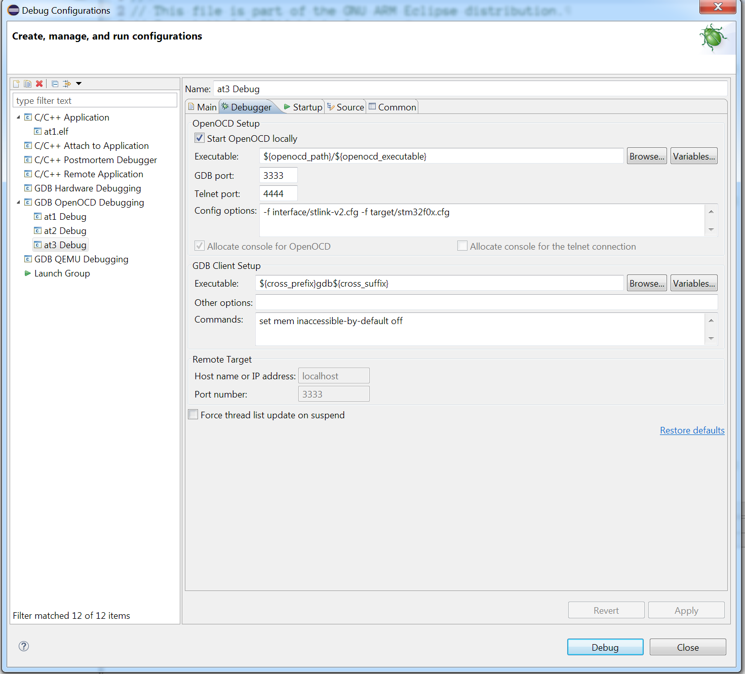
  8. Go to Run menu->Debug Configurations. Right click on 'OpenOCD Debugging' and choose New.
  9. Go to Debugger tab and put relevant OCD parameters in Config Options field. For me it is '-f interface/stlink-v2.cfg -f target/stm32f0x.cfg': 
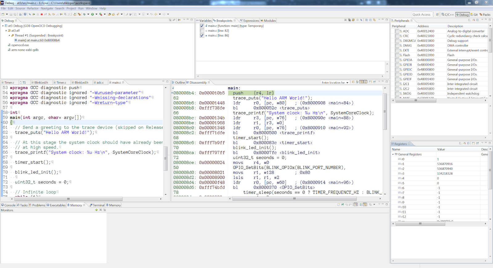
  10. Click Apply button, connect your chip to STLink, power on and run the configuration. If everything is OK, you will be stopped at your main function and your Registers and Peripherals views will be filled with relevant content. Happy debugging!

Monday, July 25, 2016

Tip Of the Day: Where is that Vrefint calibration value?

Some day I will learn to read these datasheets properly.

Meanwhile I was stuck with figuring out how to do proper ADC conversion on STM32F030.

Lets say I am measuring a voltage on ADC_IN0. The voltage is sampled by ADC and reported as 12-bit value. The value of zero corresponds to 0 Volts on input and value 0xFFF corresponds to Vdda (connected to Vdd in my case).

The problem is that Vdda or Vdd is not stable. On battery the voltage will slowly decrease. On power supply it will float because of noise. In addition, I need precise voltage value, not relative to Vdd.

All the problems above can be solved by sampling internal voltage reference provided by the chip.
So instead sampling just ADC_IN0, I need to enable VREFINT and sample ADC_IN17. Pretty cool, but there is still a problem. As the STM32F030 reference manual (RM0360) states:
The precise voltage of VREFINT is individually measured for each part by ST during production test and stored in the system memory area. It is accessible in read-only mode.
 That is fine, but no hint to where that voltage value in the system memory. Thanks Tech Overflow blog, I have found a hint about the calibration value and the actual calculation.

The actual address can be found in the chip-specific datasheet (DM00088500 for STM32F030F) in section by searching for VREFINT_CAL. Then actual Vdd can be calculated using simple formula:
Vdd = 3.3V * VREFINT_CAL /ADC_IN17

Setting up development environment for STM32F030: Hardware

I didn't find any cheap development board for STM32F030. There are pretty cheap boards for STM32F103 on ebay, but that chip is overkill for my project IMHO.

Edit: I have checked today and there are pretty cheap boards for STM32F030F. May be I have entered a wrong chip name when searched that before.

So I have bought five STM32F030, DIP20 adapter PCB, soldered and put everything on a breadboard.
Here is the resulting setup:

The upper part of the board has differential amplifier circuit for the thermistor (with a pot instead of thermistor). It is not important for now, I will describe it later.

The chip runs on 8MHz internal clock (HSI) which is more than enough for me.
The cable connection is SWD to cheap ST-link V2 found also on ebay.

Here is schematics:

Note that BOOT0 is pulled down to boot from flash memory bypassing STM32 bootloader.
The debug connector matches the ST-Link connector.

Overall - cheap, simple and does pretty good work!

Sunday, July 24, 2016

Tip of the Day: Adding file to a build in eclipse

I am a total noob in Eclipse.

Today  I have spent a few unpleasant minutes trying to solve Eclipse build issue.
I have invoked NVIC_Init() in my initialization code to configure timer interrupt.

For some weird reason linker failed: with "undefined reference to `NVIC_Init'".
After some painful minutes I found a thread on eclipse forum that solved the issue for me.

It appears that part of source files appear with "Exclude from build" flag by default. Unchecking that flag for stm32f0xx_misc.c solved the problem. Note also that project icons for included/excluded build files are different.


Wednesday, July 20, 2016

Project #1: Thermometer based on thermocouple and STM32

Why thermometer? Because I need one.

Mainly for developing printed circuit boards at home.

Thus, I need wide temperature range, lets say from 0 to 200 degrees Celsius is a must. Wider temperature range is welcome. Precision is also a good thing, but I can't estimate the acceptable error tolerance. Hope will figure out this later.

Two more requirements come to my mind at this point. The device must be as cheap as possible, so no expensive parts. The device must be mobile, but I don't want to spend too much on batteries. Will try to implement it with small rechargeable accumulator.

As far as I know there are three primary types of electronic devices for measuring temperature:
  1. Thermistors
  2. Thermocouples
  3. IC Temperature sensors a-la LM35
The latter seems to be a good option for beginners. These are ready-to-use devices with easy interface for microprocessors. A few things stop me from using them: cheap ones seem to have low upper temperature limit (LM35 is up to 150C according to the datasheet), they are not that precise (0.5C tolerance at 25C). 

Thermistors seem to have similar problem. Cheap ones seem to have upper temperature limit up to 200C-300C. Another problem with thermistors is that they need voltage to be applied to measure resistance. Since I want to measure a temperature in toaster oven (for heating up the boards), I need a temperature sensor external to the body. Longer wires mean higher voltage need to be applied. Increased power consumption is not good for the device mobility.

I am going to use a thermocouple from ebay. It is not cheap compared to thermistors, but has very wide temperature range which is a big plus.

Based on the Wikipedia article about thermocouples I need a thermistor to measure cold junction temperature. Implementing a simple devices using thermistor is probably a good start.

Finally I am going to take STM32F030F4P6 chip to control everything. It seems to have enough pins to control everything I need plus simple HD44780 display. I have bought a couple on ebay.

Getting started...

Well, starting from scratch is hard.

I tried to blog about different things a couple of times, but never really got into it. May be because I never considered things that interested me to be really interesting for a general public. May be because I am not consistent, concentrated on how things work, jumping to the next thing when the current one is not a challenge anymore. But for sure writing was always hard for me.  I remember this from the school, where I was challenged by simplest essays.

So, why am I starting over?

I am a bit into an electronics since recently. Nothing complicated, just messing with simple
microprocessors, trying to build useful things. I want pick a project and document it from the very beginning with a couple of hopes in mind:
  • I will be able to look at it in the future and see what can be done better
  • This will kind of document things so it will be easier to repeat if needed
  • I will finally practice writing
  • May be my writings on the wall will be useful for others. Or may be others will teach me a new things if my ones are wrong.
  • May be it will be fun at the end :)
Let the fun begin!